Novice shipbuilders.
We build a plywood boat from seven parts.
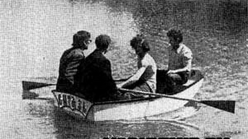
A short article about the dinghy "Jack Sprat", (), attracted the attention of our team of yachtsmen. I really liked the boat for its compactness (2.3x1.3 m), rather large capacity - in the photograph there were four adults and two children in it, and the simplicity of manufacturing technology.
We took the overall dimensions of the dinghy given in the article as a basis and made a similar plywood boat within a week.
For the construction of the boat, sheets of ordinary construction plywood 4 mm thick, glued (a mustache joint was used) to a length of 2400 mm, were used. Of these, in accordance with the sketches given, they cut out the blanks of the skin.
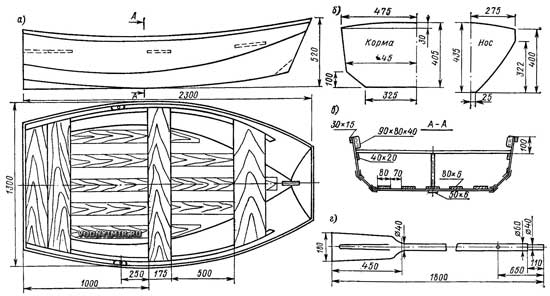
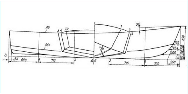
General view of the boat (a), cutting of the transoms (b), section along the midship frame (c) and sketch of the oar (d)
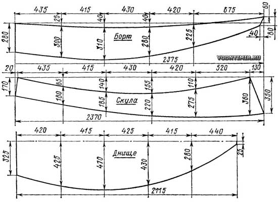
Cut sheets of outer skin.
enlarge, 1303х993, 120 KB
The body assembly looked like this. Having laid the blank of the bottom on the floor and the blanks of the zygomatic belts with the corresponding edges to it, they connected them together. First, the blanks are connected approximately in the middle of the length of the boat with copper wire clips with a diameter of 1.5 mm. Then, gradually bringing the edges closer, the same paper clips are successively placed in the bow and stern along the entire length of the cheekbone. At the ends, the shape of the hull is determined by the bow and stern transoms.
Holes with a diameter of 2 mm for staples must be drilled in advance with a step of 100-120 mm along a line beaten off at a distance of 8-10 mm from the edge of the workpiece processed to a clean size. It is better to twist the ends of the wire from the outside of the body, as shown in the sketch.
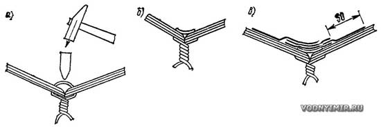
The sequence of making connections in the grooves of the skin:
a - setting wire clips and crimping them; b - the groove is ready for lining the internal fiberglass tapes; c - the layout of the tapes in the connection
In a similar way, blanks for the sides were attached to the zygomatic belts of the skin. Staples were also used to connect the skin to the transoms.
Then all joints were glued in two or three layers from the inside with fiberglass tapes. After curing the epoxy and removing the ends of the staples, the same strips of fiberglass were applied to the grooves on the outside of the case. When the transverse banks and the bow bracket (120X120) were inserted, and the fenders were glued along the upper edges of the sides, the hull acquired the necessary rigidity. The bottom was reinforced with thin pine planks glued to the plywood from the inside.
As it turned out, for the convenience of assembling the case in a similar way, it is best to use plywood of the same thickness everywhere, as provided by Jack Holt, the author of the tuzik. To increase the moisture resistance and durability of the plywood body, we glued it on the outside with two layers of thin fiberglass on epoxy resin. A “false keel” with a section of 50x6 was glued to the bottom. A small fin was placed in the stern to increase stability on the course. Styrofoam blocks were fixed under the banks. The total weight of the boat turned out to be 35 kg.
The four-year operation of the boat as an onboard dinghy on the Vityaz yacht confirmed its high performance. Quite successfully it was also used under the Salyut.
We think that by slightly reducing the height of the side, and, consequently, reducing the weight (this will be especially noticeable if waterproof plywood is used), a boat of this type can also be recommended to motorists for transportation on the top trunk of a minicar.
A. K. Kartsev, "Boats and yachts", 1979, No. 01 (077).
======================================================================
Sail on the "Chizhik".
A mast with a sail installed on an ordinary rowing boat does not yet turn it into a real sailboat. In addition to the sail and spars with rigging, which allow you to set the sail and control it, you need a rudder with an increased pen area and, of course, a daggerboard or daggerboards that keep the boat from excessive lateral drift (drift) at lateral and, all the more, courses steep to the wind - at an angle up to 40-50° towards the wind.
The placement of the crew, and therefore the arrangement of cans, on a sailing boat is always different from that on a rowing or motor boat: the crew must tilt the boat, counteracting the heeling wind pressure, and for this people need to be placed along the side. In addition, the dimensions and shape of the hull of the boat must correspond to the conditions of sailing, i.e., be designed for movement at a relatively low speed.
"Chizhik" (see "KYa" No. 24) was designed as a rowing boat with the possibility of using a low-power outboard motor: naturally, the design of the boat was designed specifically for these use cases. So, on the "Chizhik" a longitudinal middle bank was arranged for the rower; thanks to this, it is possible to give the boat an optimal trim, depending on the number of passengers, there is free space for passage along the boat, on the sides of this can you can sleep on spruces. However, the same bank is not needed at all on the "Chizhik" - a dinghy.
Basic data of the boat "Chizhik"
Maximum length 3.47m
Width overall 1.47m
Board height 0.5m
Load capacity 300kg
Power up to 5 PM, l. With.
To turn the "Chizhik" into a sailing boat, appropriate changes in the design of its hull are necessary, therefore, readers of the collection who are interested in this issue are offered two options:
Option 1 - most fully takes into account the requirements for a sailing and rowing boat, but provides for significant changes in the original project. This option is better to implement for those who are just going to build "Chizhik";
Option 2 is a compromise solution that provides for a minimum of changes to an already finished boat built according to the original drawings.
In option 1, equipment for a centerboard well, a transverse and two side cans in the cockpit and fastening of removable parts - a mast and a rudder are required. The hull of the boat is being built according to the original project, but the side stringer is brought to sp. 1. Instead of a longitudinal bank, a centerboard well is installed, which is a narrow box, open only from below, fixed with screws on glue above the slot for the centerboard in the keel. The well is unfastened by a transverse can resting on an onboard stringer.
The walls of the well and the flooring of the can are cut out of waterproof plywood 6 mm thick. The final assembly of the well is carried out after fixing the vertical racks to sp. 2. It is the well closed from above that is convenient on the Chizhik - through the open well (involuntarily it would have to be made low), with any significant excitement, water would splash into the boat.

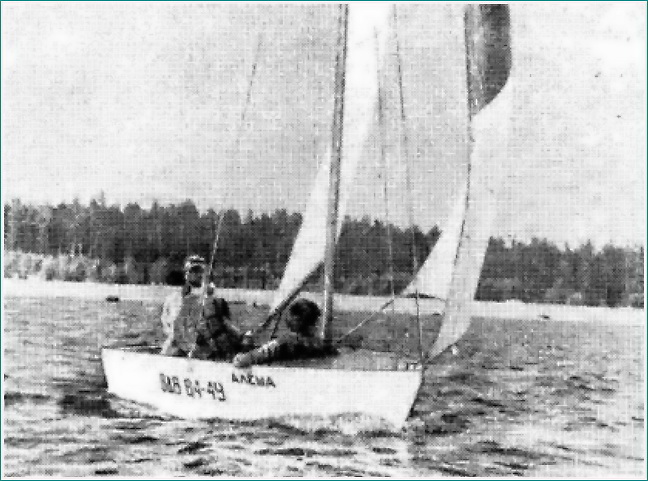
Alyosha "- the first dinghy based on the "Chizhik", built in the city of Gus-Khrustalny by V. Zhirnov.
The hull is made exactly according to the drawings given in No. 24 "KYa". A rigid can is placed across the hull, which unfastens the centerboard well. The stern fin is made higher - up to 120 mm on the transom. The dinghy is armed with a sloop with a sail area of about 6 m2. The total height of the mast, fixed with a headstay (st. cable diameter 3) and shrouds with screw lanyards, is about 8 m from the step. The mast and boom (2.0 m) are glued from pine laths and have a lip groove. The cable epaulette of the boom-sheet is hung on the transom. A block with a diameter of 25 mm slides along the shoulder strap - the sheet is passed through a block approximately in the middle of the boom and a foot block fixed on the bottom.
In connection with the tourist purpose of the boat, it is necessary to use a rotary centerboard; simpler fixed ones - “sticking” skewers cause hard blows when colliding with underwater obstacles and are inconvenient, and sometimes even dangerous when swimming in an unfamiliar area.
The daggerboard rotates on an axle, the cheeks of which are fastened with screws outside the keel to avoid drilling holes in the bottom of the daggerboard well. The dagger is rotated using a rod made of a metal bar or a thick-walled tube with a diameter of 20 mm riveted to its rear edge (do not forget to put a plug in the tube!). The rod must be very carefully bent around a circle with a radius of 250 mm (on the axis). At its exit from the centerboard well, a seal made of microporous rubber about 10 mm thick is installed, pressed by a metal plate. The hole in the rubber should be smaller in diameter than the rod. The centerboard is raised and lowered by a pusher made of a 4X30 metal strip, hinged to the rod with an M8 screw. At the aft end of the pusher, it is desirable to install a handle in the form of a wooden ball (the idea of \u200b\u200bthis design is borrowed from one old sailing dinghy).
The front and rear edges of the centerboard must be sharpened, and along the leading edge it is desirable to fix a protective fitting made of brass strip 1 mm thick. The most convenient to use are removable side cans, based on the side stringer, a thrust bar on the bulkhead of the aft locker and a strip of plywood under the transverse can. They are held in place by swivel latches, the same as the polik latches. Under the longitudinal banks, foam blocks of buoyancy must be securely attached to the hull of the boat.
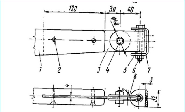
The steering wheel consists of a steering block and a lifting pen. The block is assembled on glue and bolts with a diameter of 5-6 mm from three layers of bakelized plywood. The middle part, 12 mm thick, has a sector cutout for the rudder blade. The side cheeks are 8 mm thick. The tiller is attached to the block with a metal clip bent from a sheet. The steering hinges are sawn out of a square with a wall thickness of at least 4 mm or bent from a strip and attached to the block with screws with a diameter of 6 mm. The pins (from M8 bolts with cut heads) are screwed into the threads of the hinge holes and riveted. The lower pin must be about 20 mm longer than the upper pin, otherwise the steering wheel will be difficult to install in place. The details of the steering loops, attached to the transom, are also sawn out of a square and installed on the Mb through bolts.
The rudder blade is cut out of bakelized plywood with a thickness of 12 mm and, like the daggerboard, is sharpened along the edges and protected by forging. The axis of the pen is an M8 bolt, the tightening of which is adjusted so that the raised pen is held by friction against the cheeks of the block. The upper part of the rudder blade should be sanded so that it freely enters the slot of the block. The feather is lowered into the water directly by hand; for this, a lever with a handle is provided on its rear edge. For insurance against jumping out of the loops, the steering wheel is fixed with a flat spring, fixed above the lower steering loop.
On the transom of the boat on the starboard side at a distance of 400 mm from the DP, a second pair of steering loops is installed, on which the steering wheel is hung when oaring. This is very convenient for the helmsman, since the tiller moves freely under the right hand, and does not rest against the back; rudder shift practically does not affect the controllability of the boat.
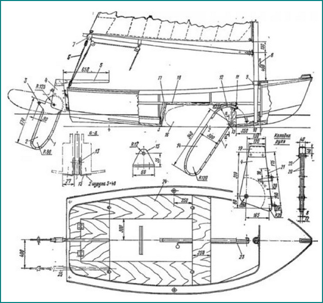
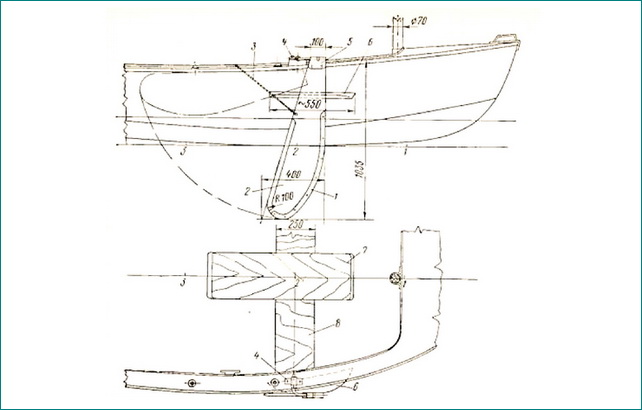
Equipment "Chizhik" daggerboard and steering gear
1 - forging from a strip 1X30; 2-feather steering wheel, bacfaner 6 = 12; 3 - handle for lifting the pen; 4- steering block; 5 - tiller, 40X40; 6 - boom sheet; 7 - boom clip, 6 = 2 mm; 8- duck for a halyard; 9- clip from the strip 3X40, fasten to the beam with through bolts M 6; 10 - step overlay, 6 = 2 mm with a rectangular hole for the mast spur; 11- sealing holes for traction 12; 12 - thrust from a tube 0 20 mm; 13 - centerboard axis - pin 0 12 mm; 14 - daggerboard, bacfaner 6 = 12; 15-cheeks of the centerboard axis, 6 = 2.5mm; 16 - well wall; plywood 6=6; 17 - stand (key) of the well 25X60; 18 - gunwale-plug of the well 25X30; 19- tiller clip, 6 = 2; 20 - side cheeks of the block, bacfaner 6=8; 21 - steering loop; 22- plywood gasket 6 = 6; 23 - daggerboard thrust; 24-board seats-banks; 25 - the position of the steering wheel when rowing.
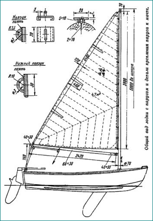
The mast blank is glued from three to four pine bars of the desired length. The cross section of the mast is above the cockpit coaming and up to about half the height - a circle with a diameter of 70 /l/l. Above this level, the front and side edges are smoothly chipped to a section on the top 40X50, below - to a section at the spur 30X50 (larger in both cases along the DP).
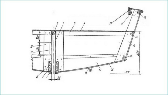
Option with screws
1 - fitting 20X2; 2 - keel 25X80; 3 - the base of the well 20 X 60; 4 - cutout for the pusher of the centerboard; 5 - well stand 20X60; 6 - gunwale of the well 25X30; 7 - from the well, 6 \u003d 6; 8 - stiffener of the transverse can 20X30; 9 - can flooring, 6=6; 10 - coaming, plywood 4X50; 11 -carleigs, 20X 25; 12 - fender, 18X30; 13 - can support bar, 18X30; 14 - toptimbers 6 = 20; 15 - cheekbone stringer, 18X30; 16 - sheathing, 6=4; 17-floortimbers 6 = 20; 18-bottom skid 20X30.
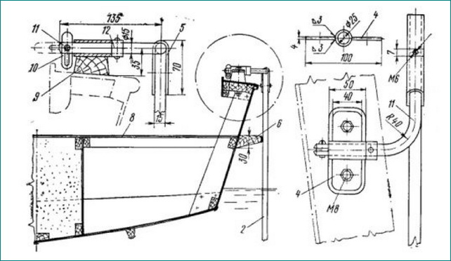
The simplest boom swivel.
1 - boom; 2- M5 screw, 2 pcs; 3 - strip b = 6 cut into the boom; 4.6 - M8 bolts; 5 - washer 8; 7 - bracket, fastened to the mast with two screws 5X32; 8 - clip b = 2.
A variant of a boat with screws.
1-forging the screw, X40, brass; 2-shverts, bakfaner 6=15/16; 3-sorlin; 4-bearing; 5-cage made of steel diameter 3; 6-support bar; 7-longitudinal seat; 8 - transverse bank 6=6; 9-pine lining; 10 check; 11 - bent axle; 12- retaining ring.
A pulley for a halyard cuts into the upper part of the mast; the swivel of the boom and the weft of the halyard are attached below. On the trailing edge of the mast, a 5X10 rail for mainsail sliders is fastened with screws through a 5X10 rail - a carefully aligned 2X20 metal strip.
The mast spur enters a 25 mm deep step socket, cut out in the rear part of the stem, and reinforced with a 2 mm thick metal bracket superimposed on top with a rectangular hole sawn into it for the spur passage. The finished mast, like all parts of the spars, is covered with a colorless varnish (oil or pentaphthalic). There is no standing rigging - shrouds and stay are not needed; the mast, along with the boom and sail, is easy to remove from the boat. If necessary, you can make the mast collapsible. In this case, the upper and lower parts of the mast are connected by a coupling made of a metal pipe with a wall thickness of about 2 mm. The 400mm long sleeve is attached with screws or through bolts to the top of the mast; in order to fix the correct position of the connected parts of the mast, a screw with a diameter of Mb is screwed into the lower part, and a slot about 20 mm deep is made in the coupling. In the area of the coupling, the rail for the mainsail sliders is mounted on short M4 screws screwed into the threaded holes.
A boom with a section of 30 X 60 is best glued in thickness from two pine bars. Towards the ends, the boom is cut along the lower edge to a height of 40 mm.
When equipped according to the second option, the boat is no longer equipped with a centerboard, but with hinged screws. On both sides in the area of sp. 2 on the inside of the skin, a support bar for the transverse bank is installed (cut on the frame), and on the outside, a bar for the stop of the screws. The transverse bank is attached to these support bars at the side and to the longitudinal bank. Below deck on both sides of the beam sp. 2 pillows are installed for the bearings of the screws.
The screws are cut out of bakelized plywood with a thickness of 15-16 mm, their vertical edges are sharpened, and protective fittings are placed along them. The upper part of the shverts is put on an axis made of a steel bar with a diameter of 16 mm, bent at a right angle. In the holder of the screw, the axis is fixed with a stopper in the form of a Mb screw without a head, screwed into the axis and going through the slots of the holder. The pivot pin is inserted into the deck bearing and fixed in it with a swivel pin. The transverse movement of the axle in the bearing is limited by a piece of tube riveted to it, from which the cage bushing was made. Shvertsy are raised by sorlins, which are laid on ducks inside the boat.
The design of the mast, boom and rudder is the same as in option 1, but it is recommended to reduce the sail area by 1 m2, taking into account the fact that the area of \u200b\u200bthe shverts is smaller than the centerboard, and the possibilities for tilting the boat due to a different arrangement of cans are somewhat worse.
Making a sailing rig is a rather complicated and time-consuming task, but the pleasure of sailing, no doubt, will more than pay for this work. However, it must be warned that the management of a sailing boat, even such a small one as the "Chizhik", requires special training of the helmsman. The best way to learn sailing is at a yacht club.
When self-studying the art of sailing, you should strictly follow the basic safety rules:
Do not overload the boat; do not take on board people who cannot swim and small children;
When sailing, the crew must always wear life jackets;
Keep a close eye on the weather; in case of danger of a squall, immediately remove the sail and sit down at the oars;
You can’t sail with a wind stronger than 4 points, and at the beginning, with insufficient experience, no more than 3 points;
Never lay sheets on a duck; always keep the halyard bay clean - ready to lower the sail;
When sailing, check if you forgot to take the oars;
Until you have gained confidence in your abilities, do not leave the area where you can be provided
immediate assistance in the event of a rollover.